bt33振荡器原理?
一、bt33振荡器原理?
电压调压器其实就是指自耦变压器。它的工作原理是指:将输入端电压不变,然后从输入线圈上取出一部分电压作为输出,当这个线圈匝数因滑臂在输入线圈上移动而改变时,输出电压也随之改变,从而达到调节输出的目的。
当我们在使用电压调压器时,有两点是值得注意的。
第一,高压器公用端必须是零线,否则容易导致触电事故;
第二,调压器没有作电的隔离,必须警慎使用,一定要具有专业的知识
二、电子元件BT33?
BT33FJ 单结管,也叫双基极二极管,配合阻容元件,可以产生震荡信号,一般用在可控硅触发电路.
三、bt33调压电路工作原理?
电压调压器其实就是指自耦变压器。它的工作原理是指:将输入端电压不变,然后从输入线圈上取出一部分电压作为输出,当这个线圈匝数因滑臂在输入线圈上移动而改变时,输出电压也随之改变,从而达到调节输出的目的。
当我们在使用电压调压器时,有两点是值得注意的。
第一,高压器公用端必须是零线,否则容易导致触电事故;
第二,调压器没有作电的隔离,必须警慎使用,一定要具有专业的知识
四、晶体管bt33怎么检测?
晶体管bt33检测方法:
用万用表电阻档判别结型场效应管管脚
一般用R×1k或R×100档进行测量,测量时,任选两管脚,测正、反向电阻,阻值都相同(均为几千欧)时,该两极分别为D、S极(在使用时,这两极可互换),余下的一极为G极
由于绝缘栅型场效应管在测量时易损坏,所以不使用此方法进行管脚识别,一般以查手册为宜。
五、BT33可用什么电路来代替?
单结晶体管BT33可以用单结晶体管BT35代替。单结管和场效应管是不同类型和功能的管子,不可互代
六、bt33单结晶体管作用?
bt33单结晶体管又称基极二极管。它的主要作用是电压随电流增加反而下降,这种作用称为负阻特性。
七、BT33哪一种耐压最好?
BT33是单结晶体管,也叫双基极二极管他耐压最好。其三个管脚的极性可利用万用表的R×1KΩ档,测任意两个管脚的正向电阻和反向电阻,直到测得的正反向电阻不变时,说明这两个管脚是两个基极(一般约3KΩ到12KΩ之间),剩下的另一个管脚就是发射极。
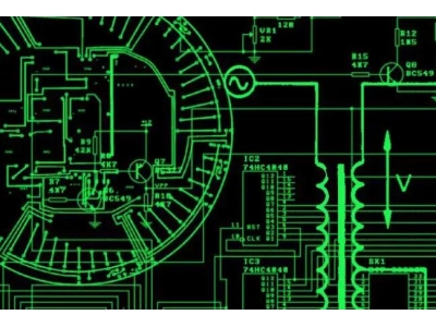
八、电路图?
画电路图需要先找好图形绘制工具 与工具相结合 能更快 更好的提高工作效率 不耽误时间 现在市场上的亿图图示功能很强大 操作简单
九、bt33三极管工作原理?
bt33三极管电路原理
接通电源前,电容C上电压为零。接通电源后,电容经由R4、RP充电,电容的电压V逐渐升高。当达到峰点电压时,e—b1间导通,电容上电压经e—b1向电阻R3放电。
当电容上的电压降到谷点电压时,单结晶体管恢复阻断状态。此后,电容又重新充电,重复上述过程,结果在电容上形成锯齿状电压,在R3上则形成脉冲电压。
此脉冲电压作为可控硅VS的触发信号。在VD1~VD4桥式整流输出的每一个半波时间内,振荡器产生的第一个脉冲为有效触发信号。调节RP的阻值,可改变触发脉冲的相位,控制晶闸管VS的导通角,调节灯泡亮度。
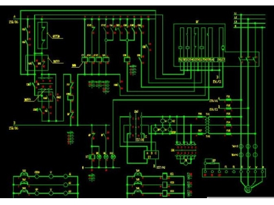
十、探照灯电路图
探照灯电路图: 理解、构建和优化探照灯
探照灯是一种广泛应用于舞台演出、户外照明和应急照明等领域的强光照明设备。在探照灯的核心部件之一是它的电路板,负责控制和供电。本文将带您深入了解探照灯电路图的构建和优化,帮助您了解探照灯的工作原理,并提供指导以构建高效可靠的探照灯。
了解探照灯电路图
探照灯电路图通常包括多个关键组件,如电源模块、控制模块、光源模块等。通过仔细研究电路图,您可以了解到这些组件之间的连接方式和信号传输原理。
在电路图中,常见的连接方式包括并联和串联。并联的组件同时接收相同的电压,但电流被分流到各个组件;串联的组件则依次接收电压,电流在各个元件之间相等。
此外,探照灯电路图中的控制模块通常包括变阻器、电位器和开关等元件,用于调节和控制亮度、色温等参数。
构建探照灯电路图
构建探照灯电路图需要具备一定的电子电路基础知识。以下是构建探照灯电路图的基本步骤:
- 确定探照灯的功率需求和光照要求。
- 选择合适的电源模块,确保其输出电压和电流满足探照灯的需求。
- 设计控制模块,包括亮度调节、开关控制和保护电路。
- 选择合适的光源模块,如LED光源。
- 根据电路图进行元件的连接和布局。
- 进行电路测试和参数调整,确保探照灯的性能符合要求。
优化探照灯电路图
优化探照灯电路图可以提高探照灯的性能和稳定性,延长其使用寿命。以下是一些优化措施:
- 选择高效能源: 选择高效的电源模块,以减少能量损耗和发热。
- 合理布局: 在电路板上合理布局组件,减少信号干扰和高温区域。
- 保护电路设计: 添加过流保护、过压保护和短路保护等保护电路,提高探照灯的安全性。
- 使用优质材料: 选择优质元件和材料,降低故障率和损耗。
- 热管理: 针对高功率探照灯,设计风扇散热模块,保持其正常工作温度。
结论
探照灯电路图是构建和优化探照灯的重要参考。通过深入了解电路图,您可以更好地理解探照灯的工作原理,并根据需求构建高效可靠的探照灯。优化探照灯电路图可以提高探照灯的性能和稳定性,延长其使用寿命。希望本文对您进一步了解和构建探照灯有所帮助。
Translated text in English: htmlFlashlight Circuit Diagram: Understanding, Building, and Optimizing Flashlights
A flashlight is a powerful lighting device widely used in stage performances, outdoor lighting, and emergency illumination. One of the key components of a flashlight is its circuit board, which is responsible for control and power supply. This article will take you through the understanding, building, and optimization of flashlight circuit diagrams, helping you grasp the working principles and provide guidance for constructing efficient and reliable flashlights.
Understanding Flashlight Circuit Diagrams
A flashlight circuit diagram typically consists of several essential components such as power modules, control modules, and light source modules. By studying the circuit diagram closely, you can understand how these components are connected and the principles of signal transmission.
In circuit diagrams, common connection methods include parallel and series connections. In parallel, the components receive the same voltage simultaneously, but the current is divided between them. In series, the components receive the voltage sequentially, and the current is equal between the elements.
In addition, the control module in the flashlight circuit diagram often includes components such as variable resistors, potentiometers, and switches to regulate and control brightness, color temperature, and other parameters.
Building Flashlight Circuit Diagrams
Building a flashlight circuit diagram requires a certain level of knowledge in electronic circuits. The following are the basic steps for constructing a flashlight circuit diagram:
- Determine the power requirements and lighting needs of the flashlight.
- Select a suitable power module to ensure its output voltage and current meet the requirements of the flashlight.
- Design the control module, including brightness adjustment, switch control, and protection circuits.
- Select a suitable light source module, such as LED light sources.
- Connect and layout the components according to the circuit diagram.
- Conduct circuit testing and parameter adjustment to ensure the flashlight's performance meets the requirements.
Optimizing Flashlight Circuit Diagrams
Optimizing flashlight circuit diagrams can improve the performance, stability, and longevity of flashlights. Here are some optimization measures:
- Choose efficient power sources: Select high-efficiency power modules to reduce energy loss and heat generation.
- Proper layout: Arrange components on the circuit board in a manner that reduces signal interference and high-temperature areas.
- Protection circuit design: Add protection circuits such as overcurrent protection, overvoltage protection, and short circuit protection to enhance flashlight safety.
- Use high-quality materials: Choose quality components and materials to lower failure rates and losses.
- Thermal management: Design fan cooling modules for high-power flashlights to maintain normal operating temperatures.
Conclusion
A flashlight circuit diagram is a crucial reference for building and optimizing flashlights. By gaining a deeper understanding of the circuit diagram, you can better comprehend the working principles of flashlights and construct efficient and reliable flashlights according to the requirements. Optimizing flashlight circuit diagrams can enhance performance, stability, and lifespan. We hope this article helps you further comprehend and build flashlights.